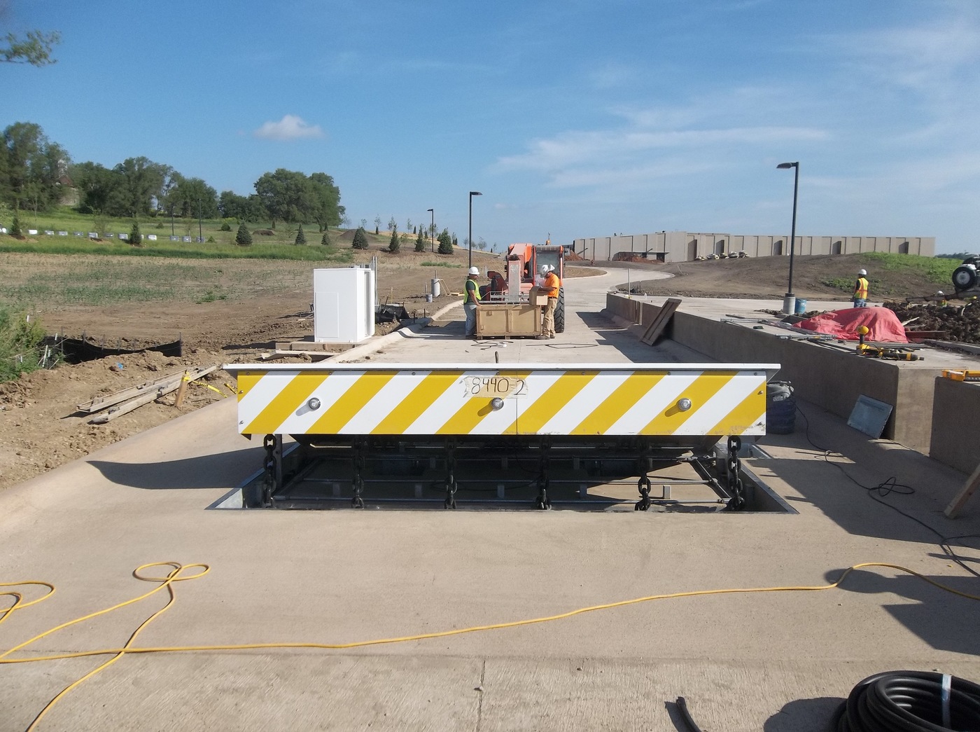
In the complying with discussion, referral is made to a surface area of a structure to which the wedge-style barrier is placed. In the illustrated personifications, the top side of the support is considerably flush with the surface of the structure. In such personifications, the wedge-style barrier might be placed straight to the surface of the foundation. In various other embodiments, the top side of the anchor might be slightly raised above the surface of the foundation or a little recessed listed below the surface area of the foundation. 1 is a front perspective sight of an embodiment of a surface-mounted wedge-style obstacle 10. As shown, the obstacle 10 is placed to a surface 12 of a foundation 14(e. g., a shallow foundation ). The foundation
Wedge Barriers
14 and the surface 12 to which the barrier 10 obstacle secured may be made from concrete. 2, the obstacle 10 is mounted to or consists of a support or subframe (e. g., anchor 30 revealed in FIG. 2 )safeguarded beneath the surface area 12. For instance, the bather 10 might be bolted to the anchor or secured to the anchor by various other mechanical fasteners. In the detailed embodiment, the barrier 10 consists of a wedge plate 16, that includes a portion that is considerably parallel with the surface area 12 when the barrier 10 remains in the retracted position. In other words, automobiles or people may pass over the barrier 10 when the obstacle 10 remains in the pulled back placement and experience slight elevation family member to the surface area 12 while on the barrier 10. As gone over in detail below, when the obstacle 10 is in the deployed position, the wedge plate 16 is held and sustained in an increased placement by a lifting mechanism of the barrier 10. Furthermore, the parts 18 may be bolted or otherwise mechanically coupled to each other. In this way, repair or substitute of one or even more components 18 might be streamlined and structured. That is, repair or substitute of single components
18 might be done quicker, quickly, and cost properly. FIG. In specific personifications, the anchor 30 might be a steel structure including plates, beam of lights(e. g., I-beams ), and/or various other structures that are secured within the foundation 14, which might be concrete. At the surface 12, a top side 28 of the support 30 might be at least partially subjected
, consequently enabling the attachment of the obstacle 10 to the anchor 30. g., threaded openings)in one or even more light beams this article or plates of the anchor 30 might be revealed to the surface area 12. In this way, screws 32 or other mechanical fasteners may be used to safeguard the barrier 10 to the anchor 30. As the obstacle 10 is mounted to the surface 12 of the foundation 14, collection of debris and other material below the obstacle might be decreased, and elements of the bather 10 might not be subjected to below grade environments. As indicated by recommendation numeral 52, the lifting system 50 consists of elements disposed below the wedge plate 16. The components 52 beneath the wedge plate 16 may include an electromechanical actuator, a web cam, one or even more camera surfaces, and so forth. In addition, the lifting mechanism 50 consists of a springtime assembly 54
The spring pole 58 is paired to a camera(e. g., web cam 80 revealed in FIG. 4) of the training device 50. The springs 60 disposed regarding the springtime pole 58 are kept in compression by spring sustains 62, consisting of a taken care of springtime support 64. That is, the fixed springtime support 64 is taken care of loved one to the foundation 14 and the remainder of the bather 10.
Not known Incorrect Statements About Wedge Barriers
The continuing to be force used pop over to this site to
the cam webcam deploy release wedge plate 16 may be provided supplied an electromechanical actuator 84 or other various other. The spring assembly 54 and the actuator 84(e. Wedge Barriers. g., electromechanical actuator)may operate with each other to equate the web cam and raise the wedge plate 16.
As stated over, in the deployed setting, the wedge plate 16 serves to obstruct accessibility or travel beyond the barrier 10. The obstacle 10(e. g., the wedge plate 16 )might obstruct pedestrians or lorries from accessing a property or pathway. If a lorry is taking a trip in the direction of the deployed visit our website wedge plate 16(e. For example, in one condition, the safety legs 86 may be prolonged throughoutmaintenance of the barrier 10.